DIY USB cables and how USB Type C is wired
Table of contents:
[0]introduction
[0.1] Often used terms
[0.2] A warning before-hand
[1] USB basics
[1.1] USB IF
[1.2] USB 2.0 vs 3.x vs 4
[1.3] USB Type A/B/C (and the mini/micro variants)
[1.4] USB Type C’s CC pins
[1.5] USB Shielding
[1.6] USB Cables and their wire gauge (AWG)
[2] USB connectors and their pinout
[2.1] USB Type A and Type B (including mini and micro)
[2.2] USB Type C
⠀⠀⠀[2.2.1] Breakoutboards for USB Type A to C cables
⠀⠀⠀[2.2.2] Breakoutboards for USB Type C to C cables
[2.3] USB Type C pinouts, in conclusion
[3] Components/tools required
[3.1] Components
[3.2] Tools
[4] Assembling a cable
[4.1] Cutting the cables to length and sliding the sleeving over it
[4.2] Stripping wires
[4.3] Tinning the wires
[4.4] Tinning the USB connectors
[4.5] Attaching the wires to the connectors
[4.6] Testing the cable
[4.7] Testing the cable with a device
[4.8] Finishing up the cable
⠀⠀⠀[4.8.1] USB Type A housings
⠀⠀⠀[4.8.2] USB Type C housings
⠀⠀⠀[4.8.3] Applying the heatshrink
[5] Finished up cables
[6] Conclusion
[7] Resources and further reading
[7.1] Resources
[7.2] FUT: Frequently Used Terms
[7.3] FAQ: Frequently Asked Questions
[8] License
[0] Introduction
When you’re dealing with electronic devices on a daily basis, you’re also dealing with cables on a daily basis. Whether that’s through wired devices or charging batteries in (primarily) wireless devices, cables are one of those constants in technology.
There are numerous types of cables - such as audio, power and networking related cables - but what will likely be one of the most ubiquitous cables in someone’s daily life is the USB cable.
Because these USB cables are a constant, it’s nice to add a bit of flair and personality to your setup using a custom sleeved cable. There are a lot of cable vendors out there and also a ton of tutorials on how to make these cables, but this thread will serve as both the theory behind USB Type C cables and how they work (or sometimes don’t work), while also showing how to make USB cables (and tackling some of the misinformation in some tutorials).
This thread will focus on USB 2.0 cables, as that is still plenty for keyboard cables (my main focus) and also because USB 3.x cables are more difficult to make due to their tighter tolerances (in terms of length matching between data cables) and because it’s more wires to work with.
[0.1] Often used terms
A larger FAQ (Frequently Asked Questions) and FUT (Frequently Used Terms) shall be provided at the bottom of this thread, this section will serve to give a bit of background information on some often used terms.
Definitions of a few very often used terms:
Cable, wire and strand:
- Strand: one single piece of metal material (such as copper or aluminium)
- Wires: consisting of either one single strand or multiple strands twisted together, also known as a ‘conductor’ (as electricity can be conducted from one side to another)
- Cable: a collection of multiple wires (such as a power cable with 2+ wires, or a USB cable with 4+ wires)
Connector and receptacle:
- Connector: The plug at the end of a cable, typically called a ‘male’ connector
- Receptacle: what a plug connects into.
Example: your phone has a receptacle that a connector on a cable plugs into.
Host-/Subdevice:
USB considers everything either a host- or subdevice. Your PC is a hostdevice, a keyboard is a subdevice and a phone has a variable role depending on what it is plugged into.
[0.2] A warning before-hand
This topic serves as an introduction to custom USB cables and will cover the most important information and show how to do it, but this should still all be done at your own risk.
Soldering and DIY electronics can be dangerous, but it doesn’t have to be with the right knowledge, safety precautions and testing.
You are the only person who knows if you can do this safely, so only do this at your own risk.
[1] USB basics
One of my past threads has a lot more information on USB and its different standards, should you want more information on that subject. This thread will cover some of the basics of USB, but mainly the parts of the specifications that serve as background information for USB cables.
[1.1] USB IF
The source of this information will be the USB Integrators Forum (IF) which has a library of documents which hold a plethora of information on USB, but it can be tough to know what to look for, which is why this thread will present the information in a more narrow path focused on making cables.
If you want more information, you should definitely check out their documents, the two particular documents I can recommend are these two:
- USB 2.0 specification document: https://archive.org/details/USB-2.0/page/n3/mode/2up
- USB Type C cable assembly document: https://www.usb.org/document-library/usb-type-cr-cable-and-connector-specification-release-23
[1.2] USB 2.0 vs 3.x vs 4
With its years of technological evolution there are currently different versions of USB in use.
USB 2.0 is still commonly used, particularly in cases where the extra speed of USB 3.x won’t be used, such as with peripherals.
USB 3.x (3.2 Gen 1, Gen 2, Gen 2x2) are newer versions of USB with higher speeds and higher power limits, but they require more wires and also a higher degree of precision when making cables, as their wires need to match up in length much more (among other complications). For reference, USB Type A/C 2.0 by default needs 4 or 5 wires, while USB 3.x needs 9 to up to 24.
With the information given in this thread and the USB IF documents linked above it’s possible to make USB 3.x/4 cables, the chance of it not working in some cases is just bigger. The USB 2.0 specification is more lenient for making DIY cables.
For those reasons this thread will focus on USB 2.0 cables.
[1.3] USB Type A/B/C (and the mini/micro variants)
USB receptacles and cables can be used with a large variation of different devices, computers, laptops, printers, phones, external hard drives, keyboards and much more. With this large variation of devices there is also a myriad of different USB connectors and receptacles, with the world moving more and more towards a universal world integrating USB Type C in their devices.
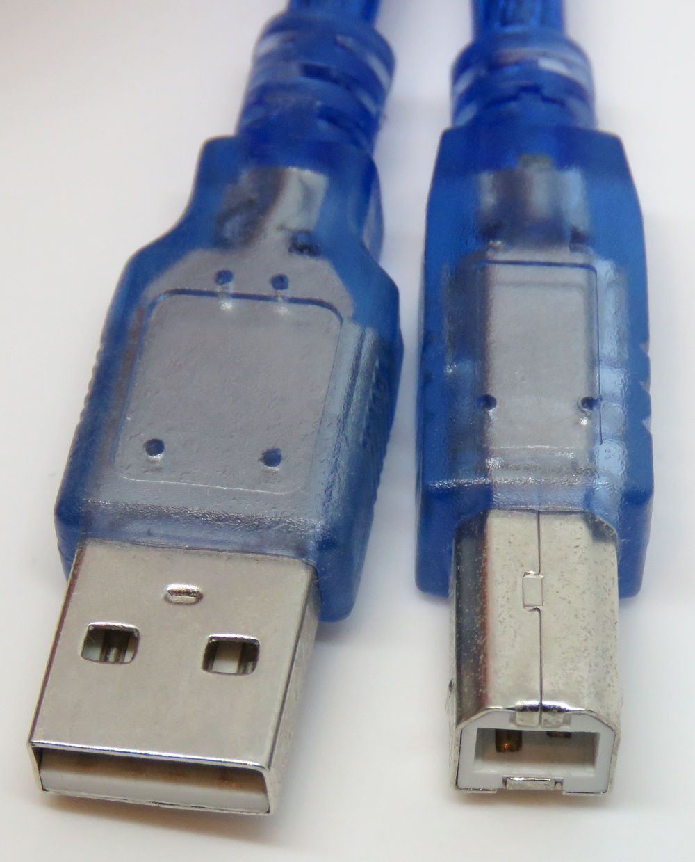
USB started off with USB Type A and Type B. Type A is the rectangular port still available on most desktop PC’s, laptops, and other host-type devices. A more square-looking port, USB Type B, is used on sub devices, such as printers, external hard drives and other peripherals (often called ‘printer connector’ nowadays).
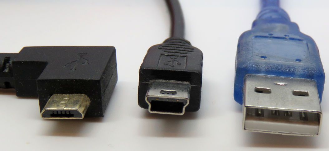
Later we got mini and micro versions of USB Type A and Type B, which are smaller USB connectors and receptacles as the larger Type A and Type B proved difficult to incorporate in increasingly portable devices (such as phones, smaller hard drives, etc.).
While mini and micro Type B were often used, there is a decent chance you’ve never seen/used mini/micro Type A; that was just not as common.
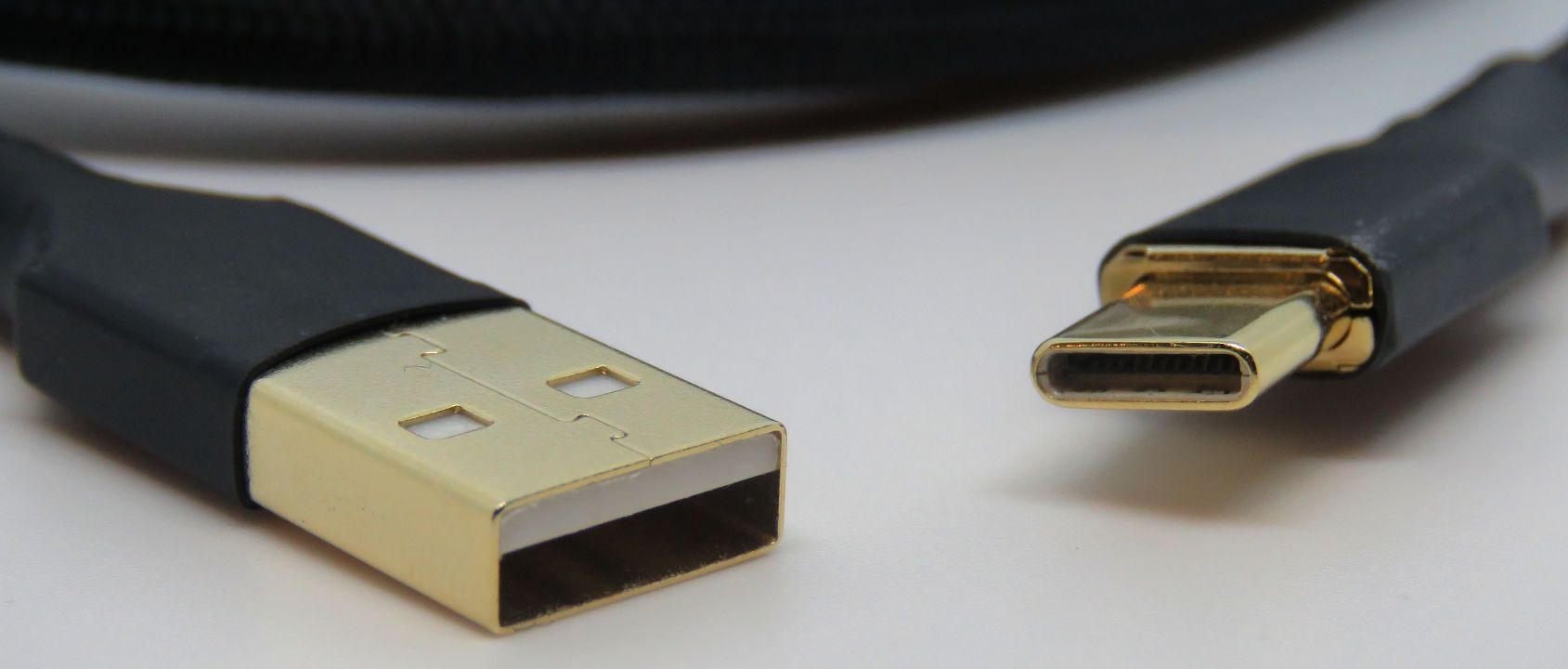
USB Type C came along later, as a receptacle designed for devices of any size; no matter if it’s a host- or sub-device. Previous USB connectors (in)famously were known not to be reversible, while USB Type C added this comfort feature.
Alongside this comfort feature, it also added some technological features, such as a way for two devices to negotiate power level (for some higher charging levels) and also a way for video to be transferred over the cable (which USB previously did not support, without the use of expensive videochips).
Some of these features in the USB Type C are optional which does make it a confusing standard, as there are different types of cables, with varying amounts of wires included (or omitted).
[1.4] USB Type C’s CC pins
One of the most defining parts of the USB Type C specifications are its CC pins, with ‘CC’ standing for “Configuration Channel”. As the name implies, these pins serve in some configuration parts of USB Type C communication.
A few of its configuration uses include:
- Deciding plug orientation (is the cable plugged ‘upside-up’ or ‘upside-down’)
- Deciding host-/sub-device functionality (as you can’t have two hard drives or two computers connect together with the conventional USB specification)
- Deciding power level (because a higher power level may be supported than previous USB standards)
- Decide if the USB device serves to provide additional features (i.e. as an audio or display accessory)
Among some more features.
This is one of the more difficult to understand parts of the USB Type C specification, which this thread will only cover the basis of (the basis needed to understand for keyboard cables).
One of my previous threads about a Ducky keyboard repair and USB specification covers this in more detail and the official USB Type C specification document holds even more detail about this technology: https://linustechtips.com/topic/1381873-ducky-keyboard-repair-and-usb-type-c-introductionexplanation/
[1.5] USB Shielding
The idea behind shielding is to protect the wires on the inside from picking up interference from outside, which could influence the signal transferred.
This shielding is often seen as optional, but for the sake of safety and signal integrity should be included.
Shield is described as a woven aluminium material, but may often be a solid aluminium material. On the receptacle and connector side shield is the metal housing of, which is the first part of the receptacle/connector that touch when connected together.
As the USB specification describes, ground and shield should be connected together on the connector side.
Often on custom cables this is left unconnected though.
[1.6] USB Cables and their wire gauge (AWG)
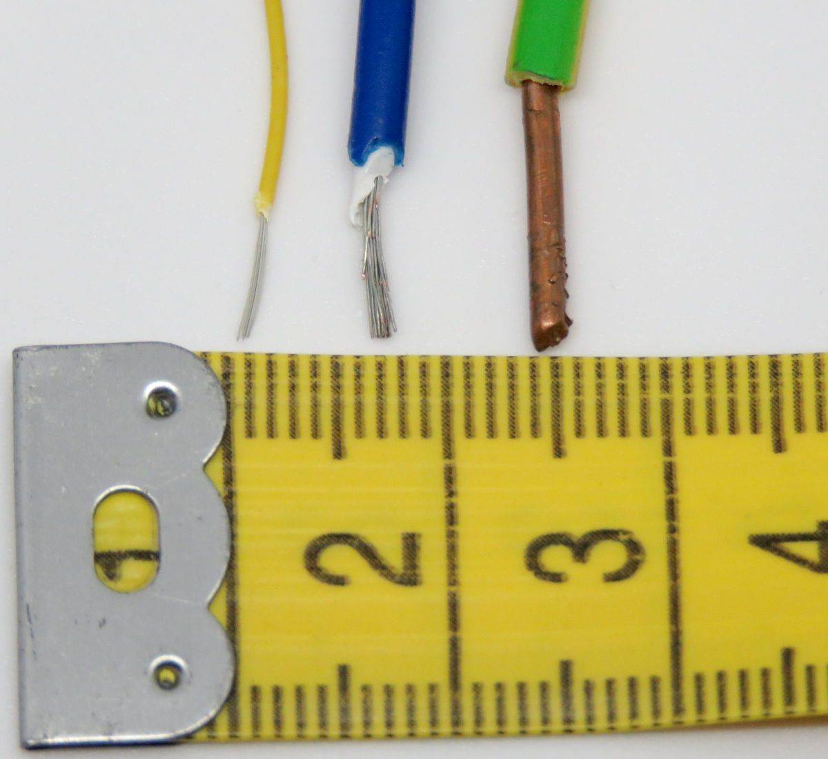
The thickness of a wire is typically measured either in AWG (American Wire Gauge) or the diameter in mm. The USB IF documents nearly exclusively use AWG measurements and as that appears to be the most common measurement given by vendors of cables/wires, that is what will be used in this thread as well.
For your convenience, a chart converting AWG to mm measurements will be included below. Be aware; the gauge of a wire is measured on the diameter of the conductive material inside, when you measure a wire do not include the outer sleeving.
The lower the AWG, the thicker the wire is. 40 AWG for example is very thin, with a diameter of 0.0799mm diameter, while 1 AWG is quite thick in comparison, at 7.3481mm diameter (nearly 100 times thicker).
A thicker wire may be needed when more power is used, which is why the USB IF includes a table on what AWG is recommended for which internal connection. Some pins regarding power for example recommended a lower AWG (larger thickness) than certain other pins in the USB connector.
Generally 28 AWG is recommended for peripheral devices (such as keyboards). Thicker wires (lower AWG) would be recommended if your cable is going to power higher power consumption devices through a USB Type C to C cable.
[2] USB connectors and their pinout
The pinout of a connector is defined by the wires needed for its communication purposes. The amount of wires is decided by the USB version in question (USB 2.0, 3.2 Gen 1, etc.) and the connectors used.
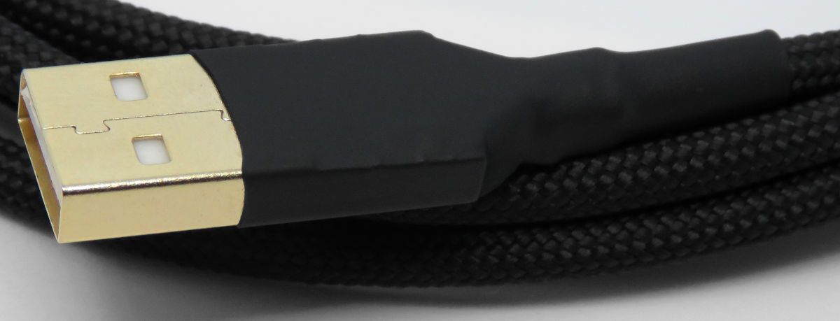
[2.1] USB Type A and Type B (including mini and micro)
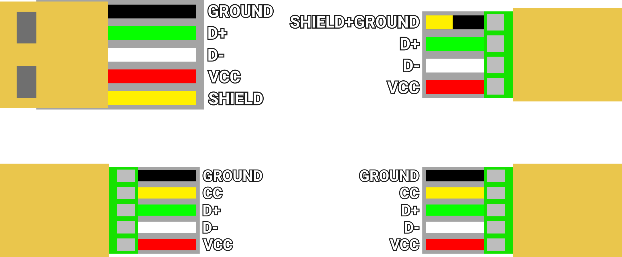
The USB specification started with USB Type A and Type B devices, which were for host- and sub-devices respectively. A USB 2.0 Type A or B connector has 4 connection points, plus the shield which is the metal housing of the connector.
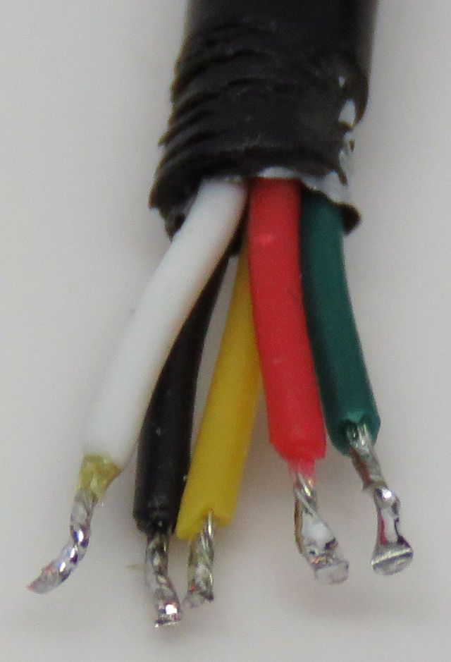
Two of these connection points are responsible for the data transfer, D+ and D- which are color coded green and white respectively. These are the two inner connection points.
The outer two connection points are ground and positive voltage (VBUS) - colored black and red respectively - which are responsible for supplying the power. These outer two connection points are often longer than the inner two, so power is connected before data.
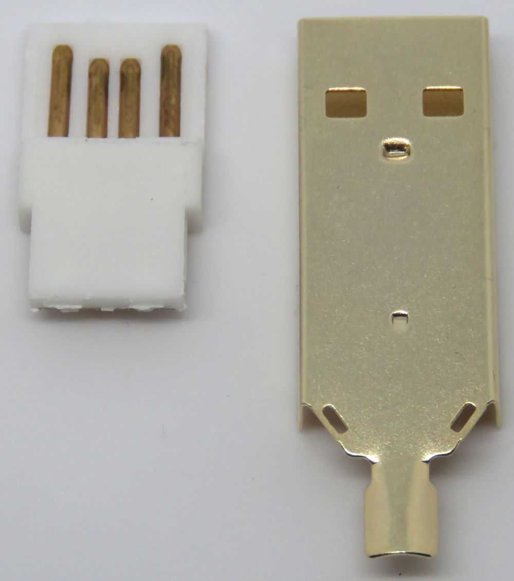
Shield (the metal housing of a connector) is recommended to connect to both the ground wire and the shielding around the USB cable. Shield is often ignored in DIY USB cables, but will be covered in a later section.
USB 3.x class cables use more wires as instead of the 4 wires of USB 2.0, it uses 9 wires. An additional two data pairs (TX and RX) and also an additional ground connection. Since USB 3.x class cables require both more wires and precision in length-matching them, they will not be covered further in this thread.
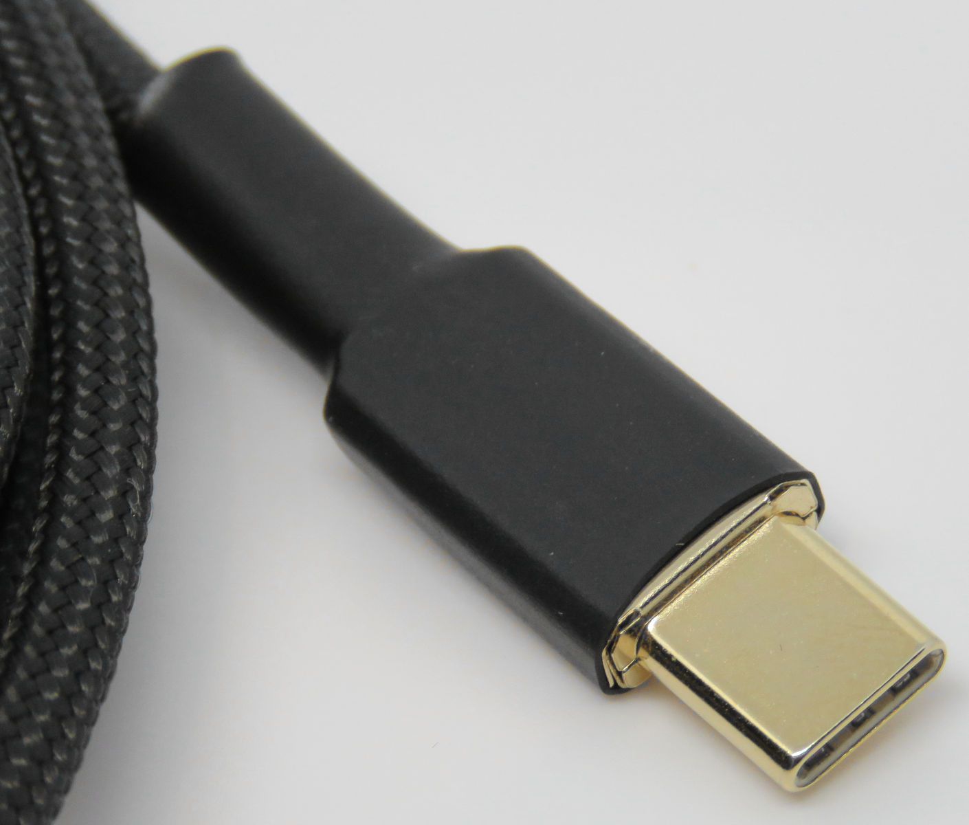
[2.2] USB Type C
USB Type C is a connector specification, with many versions and optional parts to its specification.
This thread focuses on USB 2.0, specifically on cables for keyboards. Cables for audio or video accessories, USB 3.x class cables and higher level charging cables will require extra wires in the cable to fully function. This is also why certain USB Type C cables for example don't support video out, it requires extra optional wires.
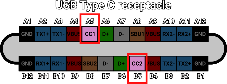
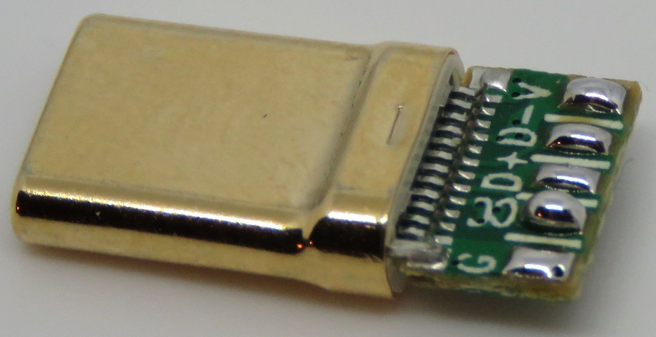
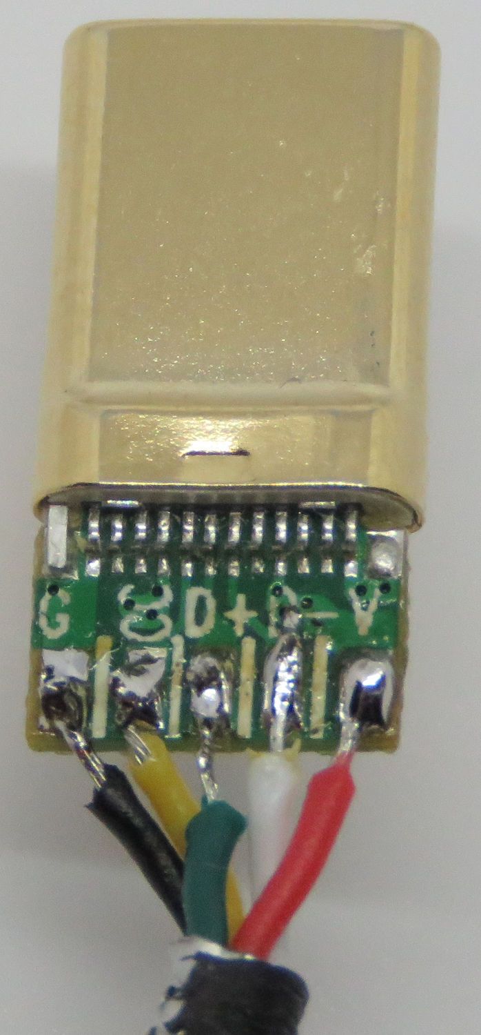
USB Type C has 24 pins inside, of which 12 are unique. For the purposes of this topic, 5 of these unique pins are used for the cables.
The 5 unique pins include the same USB 2.0 pins as discussed before; Ground, VBUS, D+ and D-, the additional 5th wire will connect to the CC pin of the USB Type C connector.
As discussed in [1.4], the CC pin is responsible for multiple functions in USB Type C equipped devices, such as deciding a host-/sub-device role, if the cable is flipped or not and more.
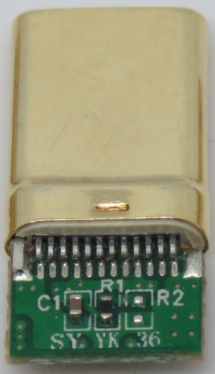
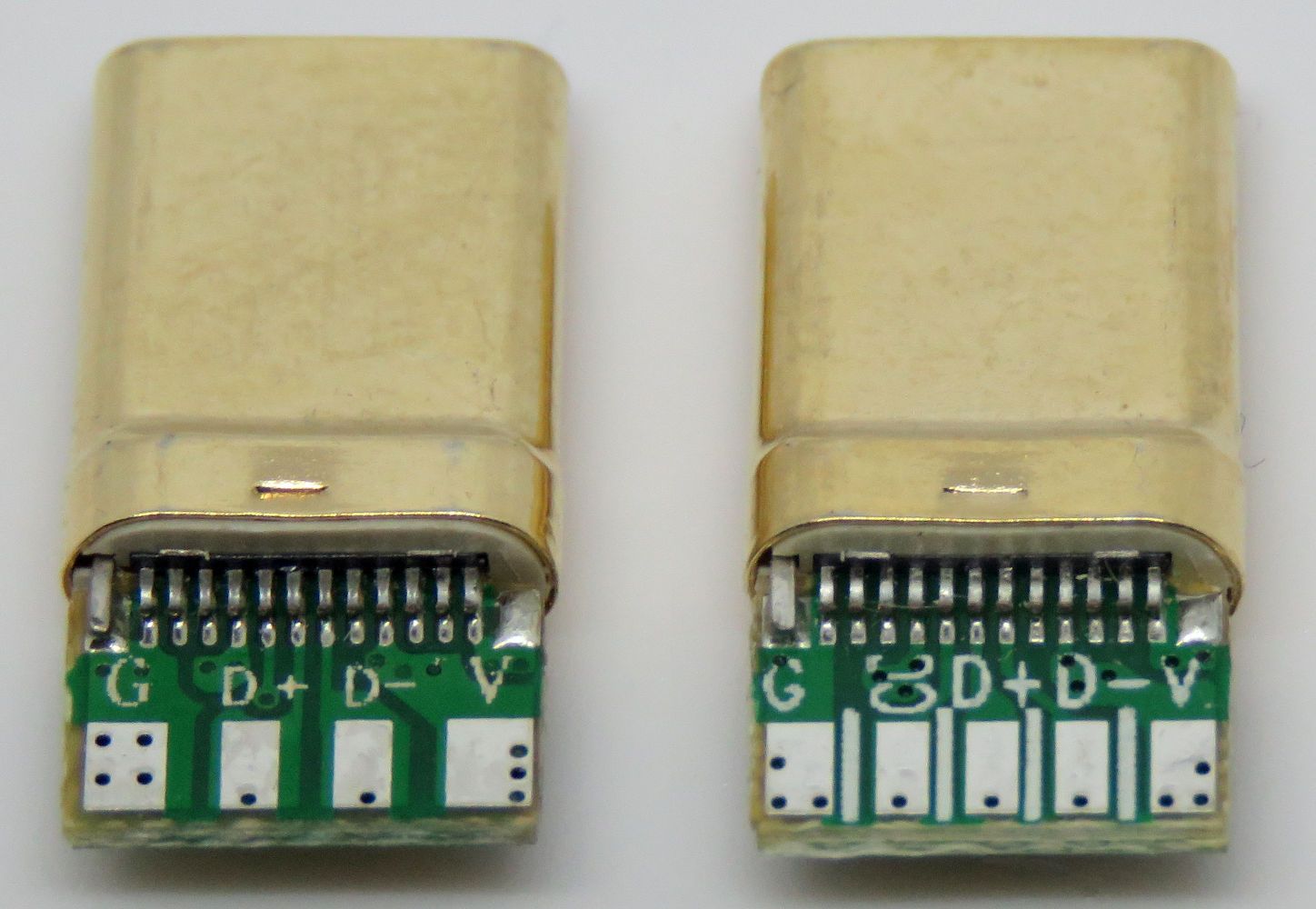
USB Type C connectors for use in DIY cables come on small ‘breakoutboards’, which include pads to solder to, which connect to the corresponding pins on the connector. How many pads and passive components are included depends on the type of breakoutboard you get and what you need to do with it.
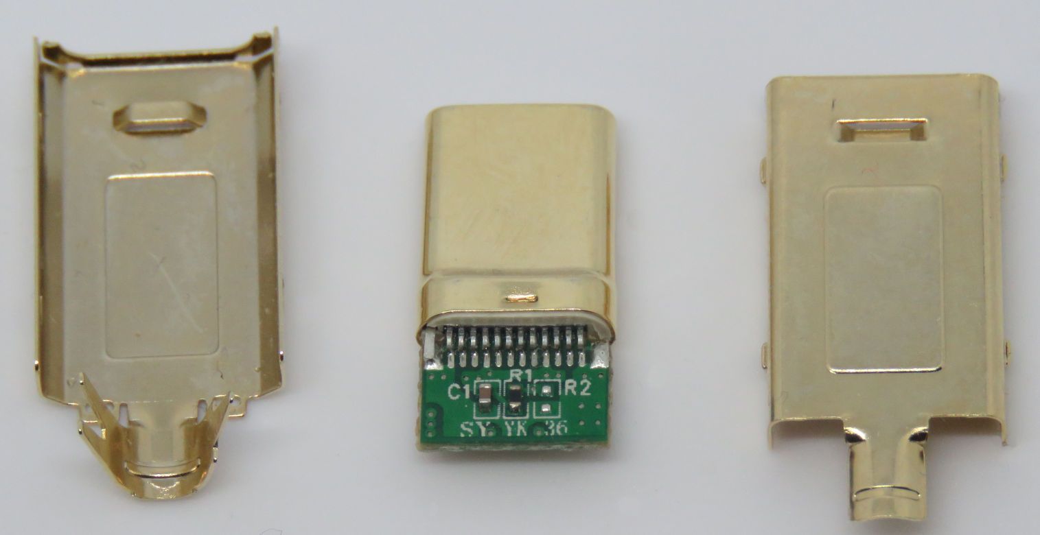
It should be noted that USB Type C breakoutboards will typically have the shield and ground connected together - as prescribed by the USB IF - without any additional work on that needing to be done.
Discussed below will be recommended types of breakoutboards for USB Type C-C or USB Type A-C cables.
[2.2.1] Breakoutboards for USB Type A to C cables
With a USB Type C to A cable, a resistor should be present on the USB Type C end of the cable, which connects the CC (A5) pin to VBUS (positive voltage). This tells the USB Type C device (such as a phone or keyboard) it is connected to a host-type device and it should act as a sub-device.
Should this cable be connected between two hostdevices (such as two PC’s or laptops), it would tell the device where the USB Type C end is plugged into “Hey, you’re connecting to a host device”. That would signify to the computer that communication is not suitable, as USB only works between a host- and subdevice.
In conclusion, for a USB Type C to A cable, the USB Type C breakoutboard must have a 56K Ohm resistor between CC (A5) and VBUS.
[2.2.2] Breakoutboards for USB Type C to C cables
While on a USB Type C to A cable, the CC pins is really only there to tell the USB Type C device what is going on, with a USB Type C to C cable it’s important that both devices know what to do.
Just to summarize what the CC pins do:
- Resistors are required in USB Type C to C cable communication for various configuration purposes, including (but not limited to):
- Whether cable is flipped or unflipped
- Power standard used
- Host-/sub-device detection
These resistors are connected from CC to either VBUS or GROUND
- Host-devices: resistors between CC and VBUS
- Sub-devices: resistors between CC and GROUND
The value of these resistors depends on the power level supported
- Generally PC’s and laptops will have 56K Ohm resistors
- Keyboards will generally have 5.1K Ohm resistors
It’s possible to get two different types of breakoutboards for a USB Type C to C cable, one for the keyboard side (with a 56K ohm resistor connected to VBUS) and another for the PC side (5.1k ohm resistor to Ground), but this would ultimately be a wasteful and worse solution than the alternative.
This cable would have two ends, one of which can only be used with sub-devices (such as keyboards) and the other side would work with a host-device (PC, laptop, etc.). A directional USB Type C to C cable, not great to have!
The much easier and sensible solution is using a cable with five wires inside. Four of them for USB 2.0 connectivity (VBUS, Ground, D+ and D-) and the 5th one to connect the CC pin between the USB Type C ends.
This would make the USB Type C-C cable reversible, as it can work on either the PC and keyboard end and would also eliminate the need for resistors on the daughterboards, as those are already included on both device ends.
[2.3] USB Type C pinouts, in conclusion
USB Type C to C and USB Type C to A cables require a different pinout, so in conclusion:
- USB Type C - A: requires a daughterboard with a 56K ohm resistor between CC and VBUS
- USB Type C - C: requires a daughterboard with 5 connections: D+, D-, GND, VBUS and CC
[3] Components/tools required
Various components and tools are needed to put together a custom cable. Certain components and tools may be optional, depending on the type of custom (sleeved) cable you’ll be trying to make.
The optional components and tools will be marked with an asterisk (*) in front. A small note will be included why it is optional.
[3.1] Components
For USB Type A - C cables:
- USB Type A 2.0 plugs
- USB Type C 2.0 breakoutboards, with 56k Ohm resistors to VBUS
For USB Type C - C cables:
- USB Type C 2.0 breakoutboard, with the CC pin (A5) broken out
Additionally needed, for either type of cable:
- 28 AWG shielded 5 core wire (in the length you need)
- USB Connectors/breakoutboards (including the metal housings for USB Type C breakoutboards)
- Cable sleeving with a 3mm diameter (in the color/pattern and length of your choosing)
- *PET sleeving: a plastic sheathing around cable sleeving, which provides extra protection to the sleeving (and a different aesthetic)(this is often called ‘techflex’, which is a brand name).
- Heatshrink tubing (1.25cm diameter, 4cm long) in the color(s) of your choosing
- Twist-tie/velcro loops; for keeping a cable bound together when assembling
[3.2] Tools
- Soldering Iron
- Solder Tin-
- Flux
- Wirestrippers
- Flush/sidecutters
- Lighter
- Heatgun* (might not be needed if your heatshrink can be shrunk with a lighter)
- Multimeter
- USB test board* (which exposes all USB pins, to more easily test a cable with a multimeter)
- Plyers
[4] Assembling a cable
Now that you know the backstory of USB, the theory about different types of cables, are aware of the wire gauges and know what tools and components you need, it’s time to actually work on the cables themselves!
[4.1] Cutting the cables to length and sliding the sleeving over it
The first thing to decide is how long you want the cable to be. Keep in mind you may not end up with the exact length you had in mind, due to the length needed to strip the cable. Any errors made with the cable may result in a smaller length too.
My recommendation is taking a certain length in mind and cutting the sleeving (and optionally PET sleeving) to that length. Be sure to use a lighter on both to singe the edge, to avoid fraying.
Now cut a piece of cable to the length you had in mind, plus another 6cm/2.5” (extra needed to strip the cable).
Before stripping the cable, slide the sleeving and PET sleeving over the cable.
After the sleeving and (optionally) PET sleeving is slid over the cable, it’s time to work on the wires on the inside, so get the sleeving/PET sleeving/heatshrink out of the way and tie the cable together with a twist tie/velcro band so it’s easier to work with.
[4.2] Stripping wires
A wire is a piece of metal (such as aluminium or copper) with sheathing over it, so to solder to the wires first the outer sheathing needs to be stripped off. There are different types of wire-strippers, so be sure to try out yours on a scrap piece of wire beforehand.
Keep in mind adding sleeving/PET sleeving to a cable after it has been stripped is annoying, so be sure to do that beforehand.
First strip the outer sheathing of the cable off (only about 1.5cm/0.6”), exposing the 5 wires on the inside. With the 5 wires exposed, strip those about 0.3cm/0.1”) leaving the bare metal available.
Next, separate the inner wires from each other. If your wires are stranded (that is they consist of multiple smaller pieces strands of material) you should twist the ends of the wires, so they will stick together better.
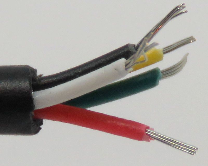
If you’re making a USB Type A to C cable, be sure to strip back the yellow wire further than the other wires, since that will ‘loop back’ to the shielding for the USB Type A connector. This is not needed on a USB Type C end of the cable.
Now it’s time to tin the wires, which is adding some solder to them, which will make it easier to solder them to the USB connectors.
[4.3] Tinning the wires
Be sure to follow all the needed safety precautions when using a soldering iron. Only solder in a well ventilated area, clean your hands after soldering, wear safety goggles and only do it if you’re comfortable with it.
Soldering can be easy, but only if you take the right steps in making sure you’re safe while doing it.
Turn on your soldering iron - somewhere in the 300/350°C range is plenty - and let it heat up. Tinning the wires involves touching the iron on one side of the cable (the bottom is the easiest) and feeding some soldertin from the other side (like the top).
Only a little bit of solder is needed to coat the wire. The heat of the solder iron/solder will melt away some more of the sheathing, which is fine. That is why it’s recommended to only remove a little of the sheathing of the inner wires.
If you have a lot of excess length to the inner wires, cut them to the same length. You don’t need too much metal exposed for the next step.
[4.4] Tinning the USB connectors
To make it easy to attach the wires shortly, it’s best to also tin the pads on the connectors.
When you heat up the contact points on the USB connector, other parts of the connector may get hot too (especially the shield part of the USB Type C connector when heating up ground).
Not a lot of solder is needed on the connectors, just enough so the cables will easily solder to them. The plastics on a USB Type A connector may get melted a bit, but as long as it’s just a minor bit of damage it doesn’t matter.
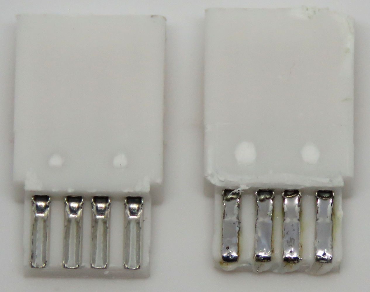
Now that all the connection points have tin applied to them, it’s time to actually solder the wires to them.
[4.5] Attaching the wires to the connectors
This is your last chance to do anything with the cable itself. You should’ve checked before-hand, but just make sure:
- The sleeving (and optionally PET sleeving) are on the cable
- You have the wires all tinned
- If you’re making a cable with a USB Type A end, make sure the yellow cable is stripped and tinned further on the USB Type A side of a cable
Now it’s just about soldering the wires to the connectors. It may be best to use a clamp of some kind to hold the USB connector in a way you can easily push a wire into its connection point.
Apply a bit of flux to the connection points (this just makes the solder cool down with a shiny finish), heat up the solder on the connection point and solder the wire to it.
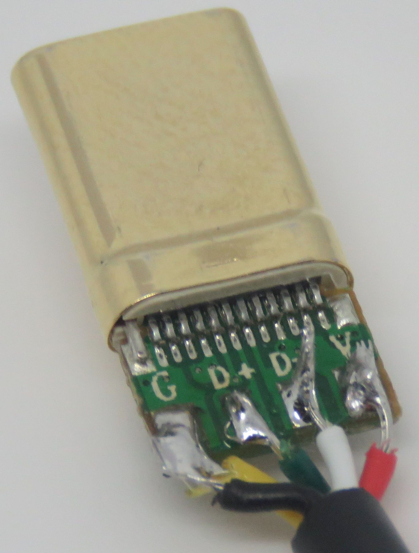
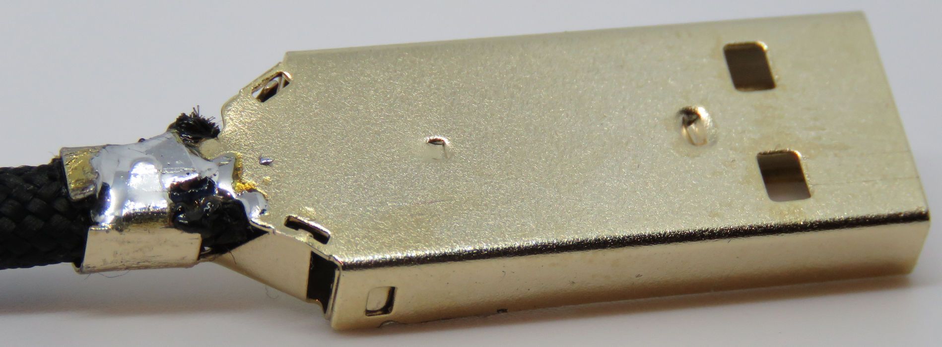
14_IMAGE_USBCATTACHED
With a USB Type C to A cable, the ground and shield wire both connect to ground
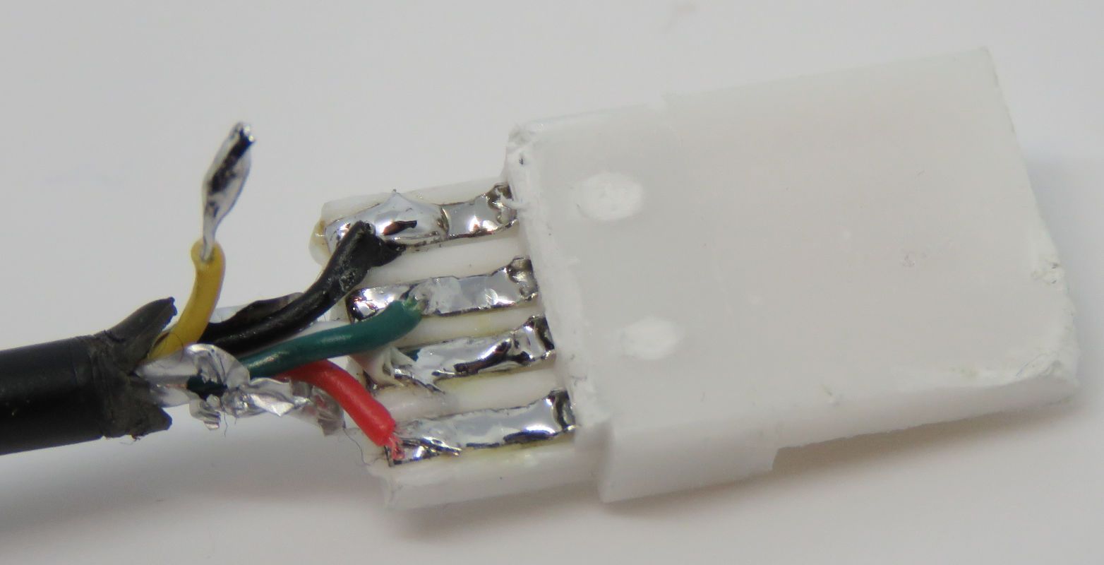
After soldering the wires, if you’re making a cable with a USB Type A, the 5th yellow wire (which was stripped further and had tinned applied to it fully) should still be free. This will be handled in a later step.
[4.6] Testing the cable
You should have a working cable now!
Before you plug it into a device it’s best to test the cable for continuity first though, to make sure there are no shorts on the cable.
With a USB Type A connector the connection points are so large you can easily grab a multimeter, put it in continuity mode and check if the cables aren’t touching each other.
With USB Type C it’s a lot easier to check using a small test board, but it is still easy to check for shorts using a multimeter on the connection points.
Make sure there are no shorts before proceeding further!
[4.7] Testing the cable with a device
Once you’re sure there are no shorts on the cable and it visually looks good, you can test the cable with a device. You can test it with a keyboard, or to charge your phone, that way you know the cable is good in terms of data transfer (the former test) and also with transferring power (the latter test). Be sure to test a USB Type C end of a cable in both orientations (upside-down and upside-up)
Of course only do this once you’re sure there are no shorts and it all looks good, so always do this at your own risk.
[4.8] Finishing up the cable
Now that the cable is confirmed working, it’s time to work on the finishing touches of the cable.
Add some hotglue to the wires on the connectors. This hotglue acts both as a strain relief (protecting the wires from repeated bends) and also makes sure the wires don’t touch each other.
Make sure the hotglue doesn’t stick out to any one side though, so the housings can still be fitted over the connectors. A good way of avoiding this is by applying the hotglue and pushing it down with a flat metal object (such as tweezers). Be careful though, hotglue - as the name implies - is hot.
Once the wires are in place, grab the housing pieces for the USB connectors used. Both USB Type A and Type C connectors use two housings, but use a different way of being put together.
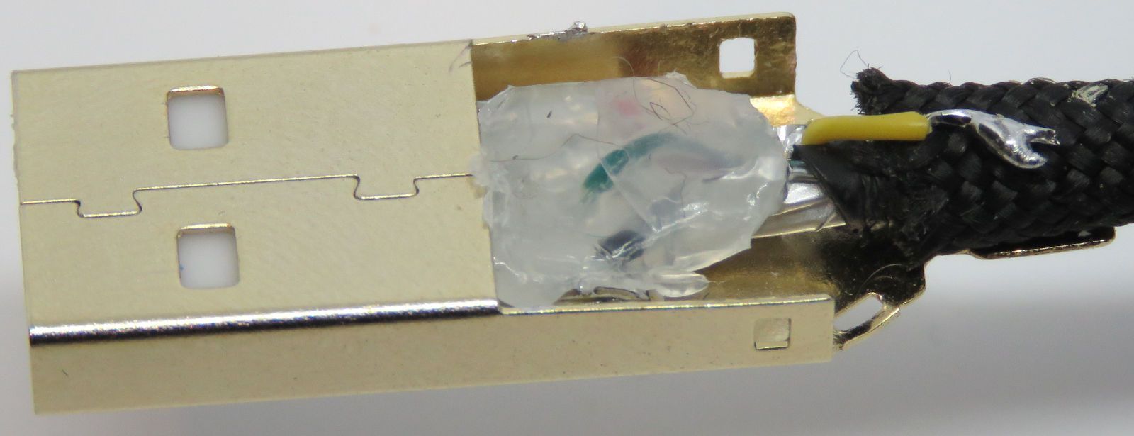
[4.8.1] USB Type A housings
With a USB Type A connector, slide the plastic piece in the metal housing, with the wires facing up and the yellow (tinned) wire routed back as shown above. Apply some soldertin to the closing part of the housing, which will solder to the shield wire later.
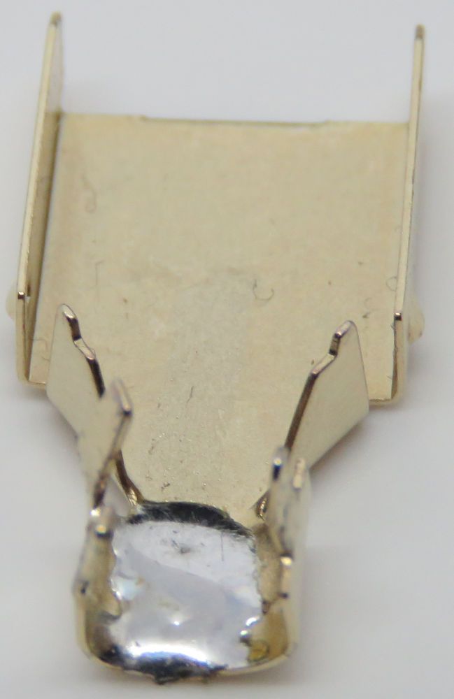
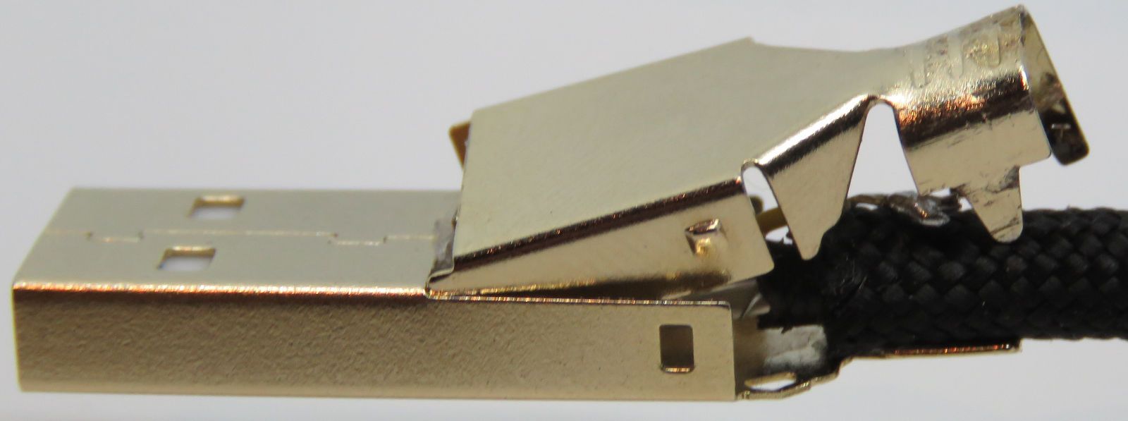
To make sure the shield is actually connected between both USB ends, grab a multimeter and measure for continuity between the shield on both USB ends. If there is continuity, it’s recommended to heat up the shield part on the USB Type A connector, to heat up the solder and make the two join together properly.
Now grab a set of pliers and squeeze the locking mechanism together, doing your best to keep the cable a circular shape and not puncturing any wires.
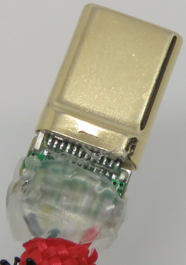
[4.8.2] USB Type C housings
The housings for USB Type C just get placed on the connector, with the raised bits of the housing in the divots of the connector. Now just like with USB Type A housing, squeeze the locking mechanism shut (no shield cable needed this time).
Soldering the housing closed is recommended for both type of connectors, as it ensures the connector can’t open anymore. Apply some heat to the housing where it is clamped together and add some solder.
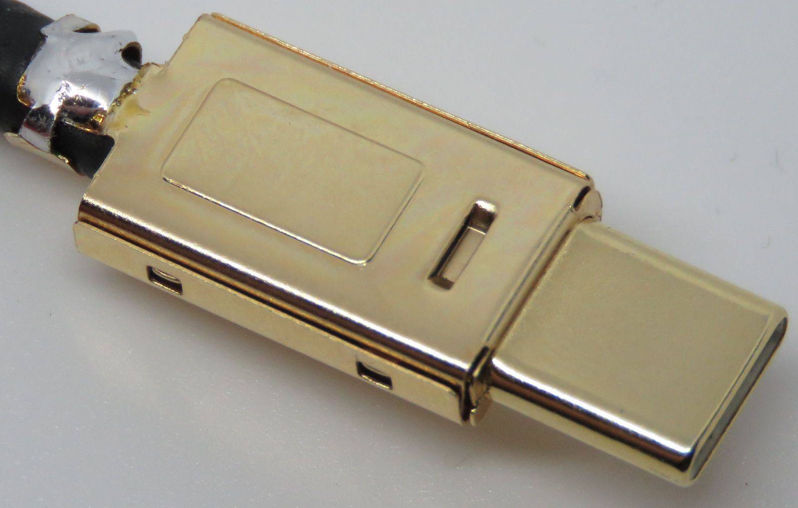
[4.8.3] Applying the heatshrink
The larger 1.25cm diameter heatshrink is to apply to the connectors, to give it a neater look and more of a place to grab the cable. Some USB housings will come included with plastic outer shells, which can be used instead.
Slide the heatshrink over the USB connector and evenly heat it up with a heatgun - on its lowest setting for easier application of even heat. Keep in mind the USB connector will get warm or even hot, so don’t grab it during this process.
Make sure the heatshrink is in the right position when starting this process too, touching the heatshrink when it’s hot may leave marks on it. With USB Type C connectors it’s easy to see where the connector will be plugged in to, while on USB Type A you should plug in the cable to something to see how far the heatshrink would reach. Of course unplug the cable when applying heat for the heatshrink.
The heatshrink often won’t give a fully even appearance - mostly due to there being too much size variance between the widest part of the connector and narrower cable - but this is only an aesthetic concern.
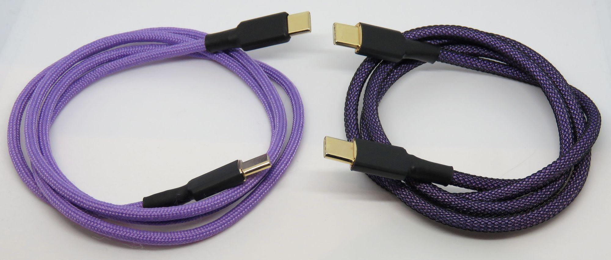
[5] Finished up cables
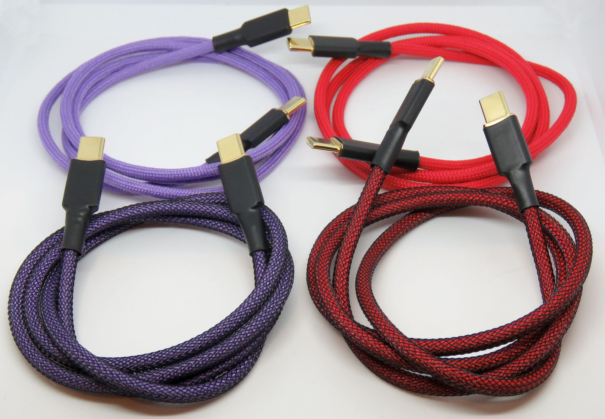
Now with all those steps behind, you should have a working and finished cable!
With the amount of variations you can choose (color of sleeving, heatshrink, etc. choosing to use PET sleeving, USB C/A, etc.) there are various types of cables that can be made.
Here are some cables I’ve made so far:
[6] Conclusion
With the information given above, including the steps to make a custom sleeved cable you should now have a better idea of how they are made and what makes them work.
It should also shed some light on why the USB Type C specification - especially in terms of cables - can be such a mess, with optional portions of the specification and more wires being present (especially compared to previous USB connector types).
The USB specification is a mess, but it’s very interesting to see how they are attempting to make the world of technology better interconnect with each other. Learning more about the specification during the process of learning how to make cables was engaging to say the least.
Custom cables may not be very economical - considering sleeved cables are often very reasonably priced compared to buying the supplies + tools yourself - but does present an interesting challenge and way to further customize your setup (including color, length and styling of the cable).
I hope you enjoyed learning about the USB cable specification and custom sleeved cables as much as I enjoyed writing about it. Should you have any questions, criticism and/or feedback I would love to hear about it.
If you’re looking for more information, I will leave links for further reading in the resources section below. Just as a heads up, the USB IF cable specification was by far the main source for this thread.
[7] Resources and further reading
[7.1] Resources
USB IF document library: https://www.usb.org/documents
- USB 2.0 specification document: https://www.usb.org/document-library/usb-20-specification
- USB Type C cable assembly document: https://www.usb.org/document-library/usb-type-cr-cable-and-connector-specification-release-22
AWG to mm (and vice versa): https://www.electricalworld.com/en/AWG-to-MM-Cable-Conversion-Guide-and-Calculator/cc-51.aspx
[7.2] FUT: Frequently Used Terms
Cable related:
- Strand: one piece of metal material, such as a copper or aluminium strand
- Wire/conductor: multiple strands that form a wire together
- Cable: multiple wires, that form a cable together
- Sheathing: the rubber material around wires/cables that insulate them
- Sleeving: the cloth material around a cable
- PET sleeving: often known as techflex, a plastic material that can be used around sleeving for a stiffer and better protected cable
Working with wires:
- Stripping a cable: removing (part of) the out sheathing to expose the wire(s) on the inside
- Tinning a cable: applying solder to attach the wire to a USB connector
- Length matching: making sure the length of a pair of data wires (such as D+ and D-) is the same, especially important on USB 3.2 class cables
USB (connectors):
- USB: Universal Serial Bus, a set of standards surrounding different types communication for peripheral and host devices
- USB IF: the organization that oversees the USB specification
- USB Type A/B/C: different types of physical connectors, see [1.3] for more info
- Mini/Micro USB: smaller USB connectors introduced when more portable devices were making its way on the market, see [1.3] for more info
- USB 2.0 vs. 3.2: different generations of USB products, with increased speeds and functionalities, see [1.2] for more info
- USB Type C: the newest USB connector, which features a reversible plug design and a large list of features (many of which are optional)
- CC pins: The Configuration Channel pins on the USB Type C specification, which aids in the communication between devices to make them agree on what part(s) of the specification can(‘t) be used
DIY cables:
- Connectors: USB plugs which can be used for the purpose of making a USB cable
- Breakoutboard: The connection points on USB Type C are too small to easily solder wires to, a breakoutboard is a small PCB which features some pins ‘broken out’ to small pads to solder to
- USB shield: the housing of a USB plug serves as the ‘shield’ connection, which shall be connected to ground
- Heatshrink: a rubber material that can be used around cables to both protect the wires on the inside and also gives a different aesthetic to the cable
[7.3] FAQ: Frequently Asked Questions
Q: “Why make your own cable instead of buying a custom sleeved cable?”
A: Making these cables was 50% about wanting to learn about cables (and conveying said information), 50% from curiosity. It’s often more economical to buy some cables.
[8] License
This thread is licensed under the Creative Commons Attribution-ShareAlike 4.0 license (CC BY-SA 4.0).
The short explanation for this license can be found here: https://creativecommons.org/licenses/by-sa/4.0/
The full license can be found here: https://creativecommons.org/licenses/by-sa/4.0/legalcode
Under this license, you are permitted to share and adapt this content how you see fit, provided you credit this original guide and use the same license (CC BY-SA 4.0).
Comments?
Leave us your opinion.