[Build Log] ThinkPi - Old Chassis, New Tricks
[Disclaimer]I am simply reposting my build logs from the LTT forum to reach a broader audience.
Project ThinkPI
You might be wondering, what the heck is this title ?is it a ThinkPad ? Did he mean ThinkStation ? What’s with the Pi ? Can I have some ?NO. . you can’t.
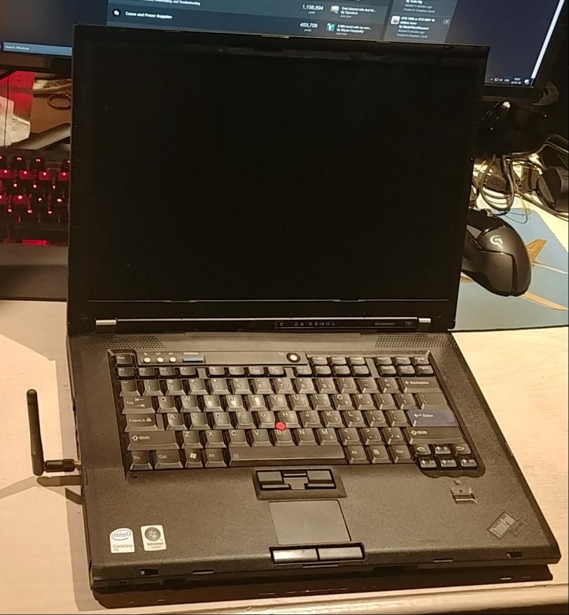
This is a little project of mine, where I will take this old 2007 T61 Thinkpad, gut it, hack the heck out of the frame, and shove a Raspberry Pi 3b+ in it !you may wonder. Is this possible ? will it fit in ? what about the display ? the keyboard ? how does that all work ?Well, this is where this goes from a simple computer, to a true project laptop.
Why I want this :I’ve been doing some fun stuff with an SDR, or a Software Defined Radio. witch lets you do tons of stuff with radio frequencies (receiver only for my unit) I can listen to ATC, the ISS (given I have a proper antenna) and the real purpose of this : Weather satellites !
So then, I wanted a Pi to run this at first, small, compact, powerful. but then I realized, I need a monitor, keyboard, storage…Yeah, I could have took my existing laptop… but I already had a PI I bought a PI !And it wouldn’t be as cool without one.Tons of people have done “Pi laptops”, but they are mostly either 3d printed, thick and flimsy, or they’re plastic kits that are super tiny, and quite frankly unusable.
Project Milestones :
- Gut it
- Gather components
- Get the monitor working with the Pi (potential deal breaker) || Works as of Jan 14th 2019
- Get the keyboard working with the Pi (Has been done before, though most of the projects I’ve seen are abandoned, even the most recent ones.
- Power [EDIT : 26th of Feb 2019 : Thanks to @CUDAcores89, I now have the knowledge to build my own pack reusing the batteries I had. I should start work on this in a few weeks when parts arrive.]
- Fit it all in
Components :
- Raspberry Pi 3b+
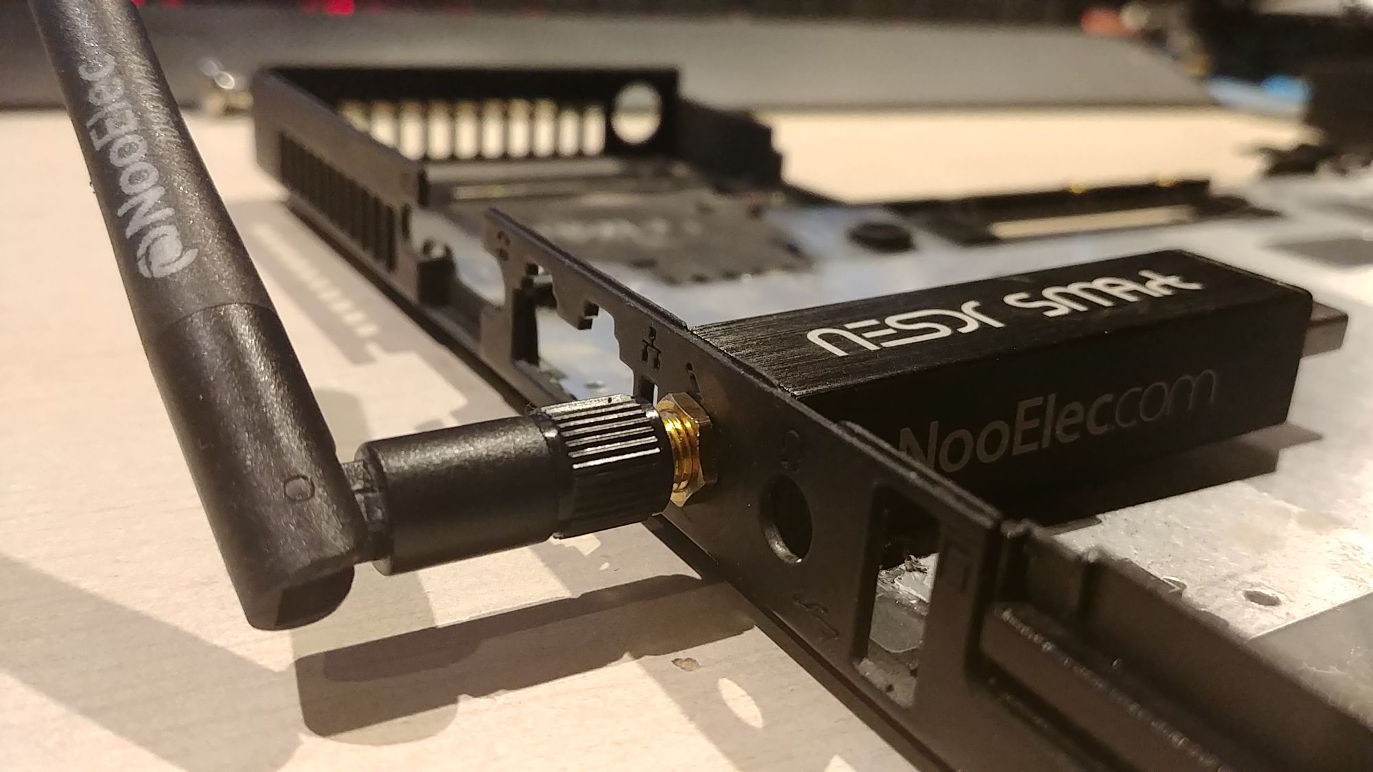
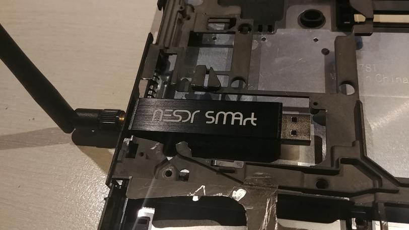
- Nooelec NESDR SMART Software Defined Radio 1
- Thinkpad T61
- Corsair Force LS 114gb Sata2 SSD
- Some SATA-To-USB adapter
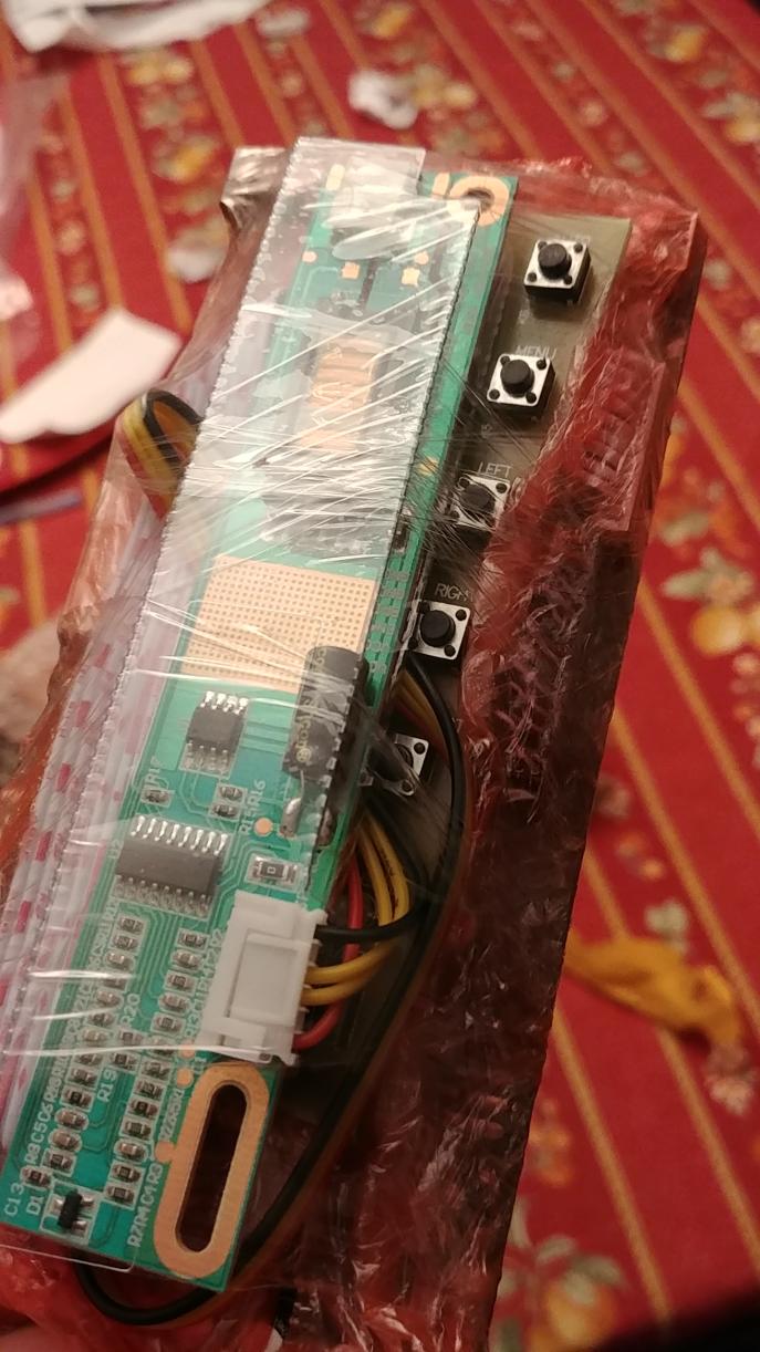
- HDMI+DVI+VGA LCD led Controller Inverter Lvds Board Kit for LP154W02(B1)(K6) (Controller for the monitor)
- Some thinkpad kbd to usb controller (soon)
- Some power solution (soon)
- Potentially some replacement for the fingerprint scanner & the trackpad (those tiny keyboard w/ trackpad gutted maybe ?)
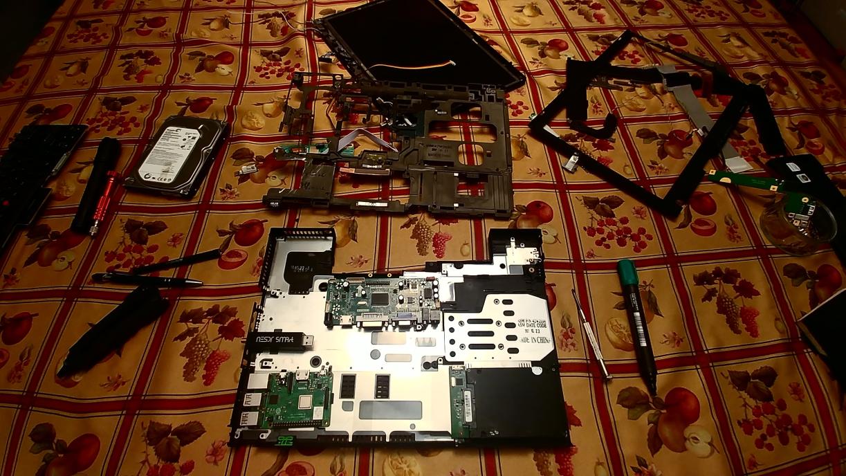
I will keep this post updated as I go along. I will post an update post for anyone who wants notifications on this.Here’s a few pictures of the early stuff :
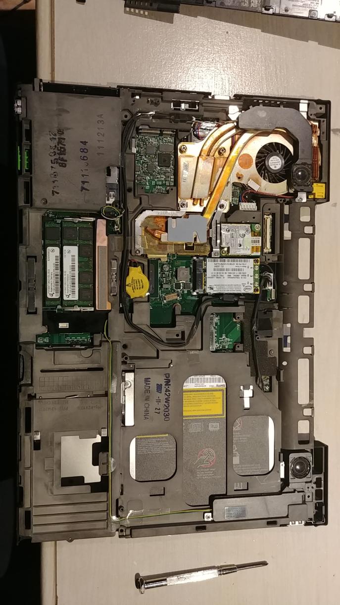
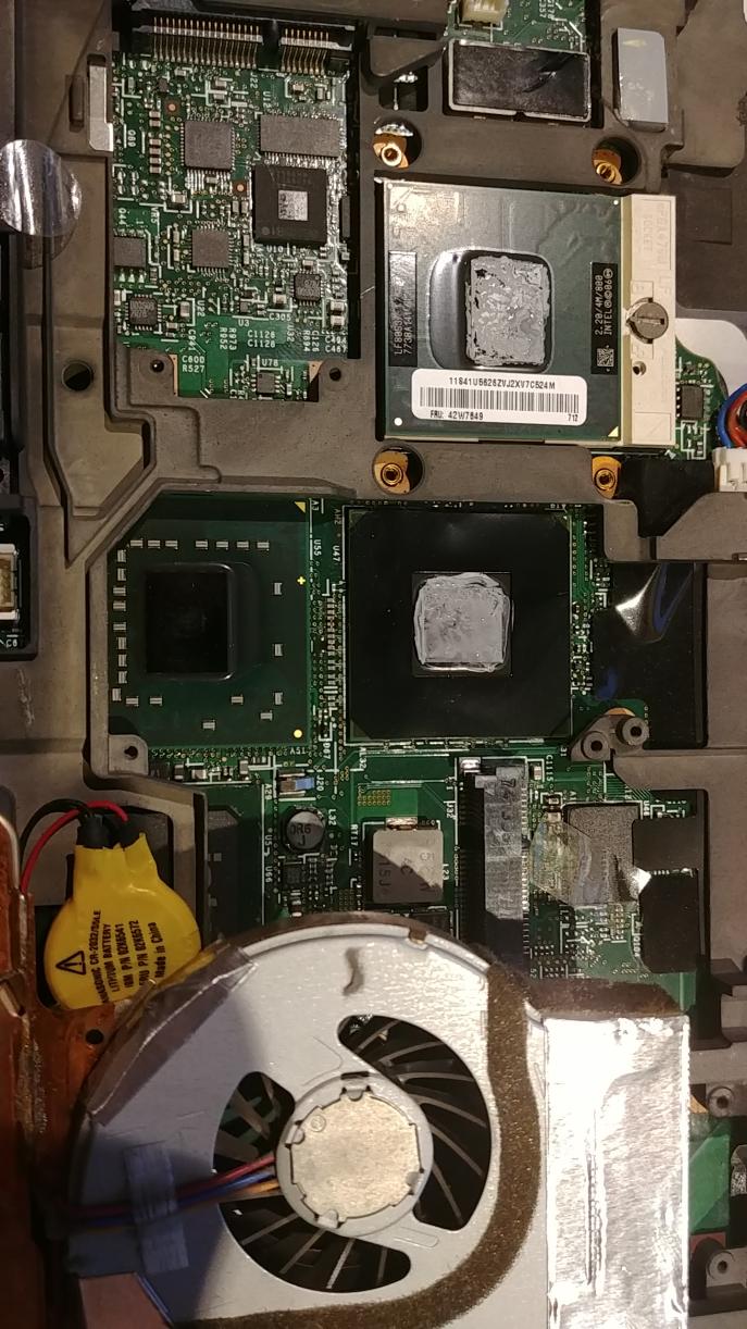
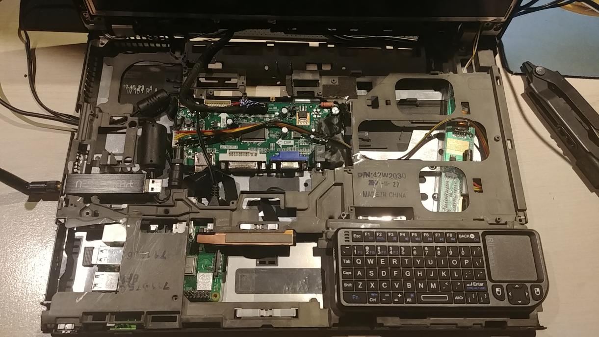
Disassembly :
From this, I have kept the external body, the frame, the keyboard, the monitor and the speakers.
The early fitting of the components :
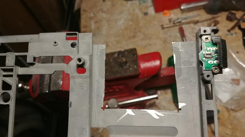
In here, there's the SDR (witch fits perfectly through the 3.5mm jack ! made to be !) the Pi and (although hidden) the SSD.
I also had to cut the frame a bit to fit some stuff. The pi is slightly too tall, but the bulge is not toooo bad.
Update #1
See with your own eyes !
I got the display controller In its neat little package. (Fig.1)
And holy shit it works !
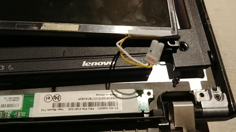
Now you see, I was a bit scared at first, since the connector didn't match the one on the ribbon cable of the whole monitor unit.
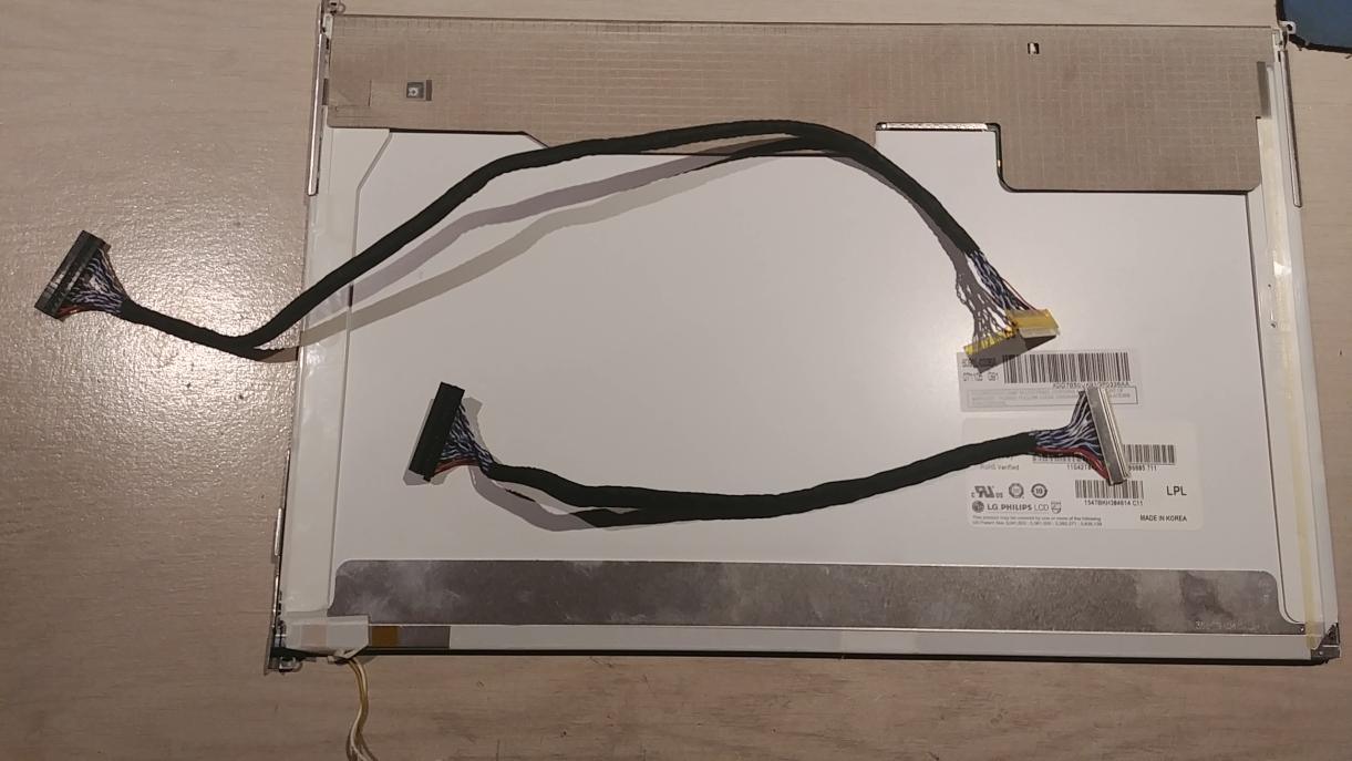
After some more digging and disassembly, I found out that the cable in question is also used for the top led, the backlight (more on that later) and the activity led on the bottom.
The actual panel connector is right smack in the middle of the panel, on the back.
So I connected it !
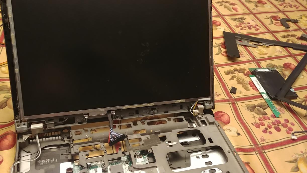
and it.. wait.. does it work ?
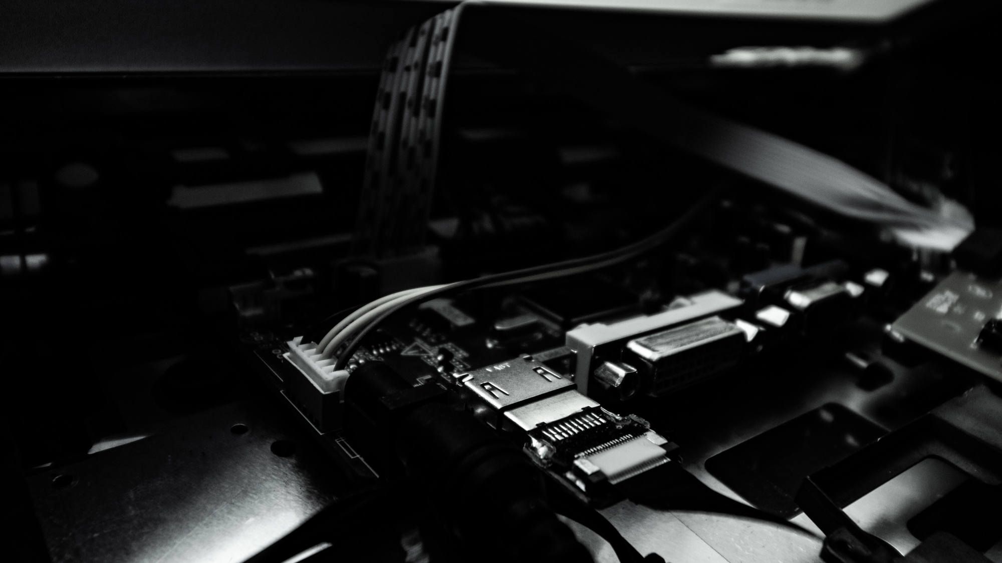
hard to see... (Fig.2)
Oh ! Right ! The backlight !
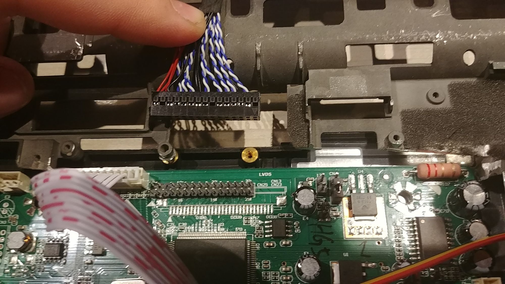
You see, the backlight is controlled separately from the display connector. the power for it comes from the separate board of the activity led (sounds weird, but the backlight is at the bottom, next to that board) and I then realized, wait ! there's another board with the controller that has a plug that oddly resembles the backlight's cable ! (Fig.3)
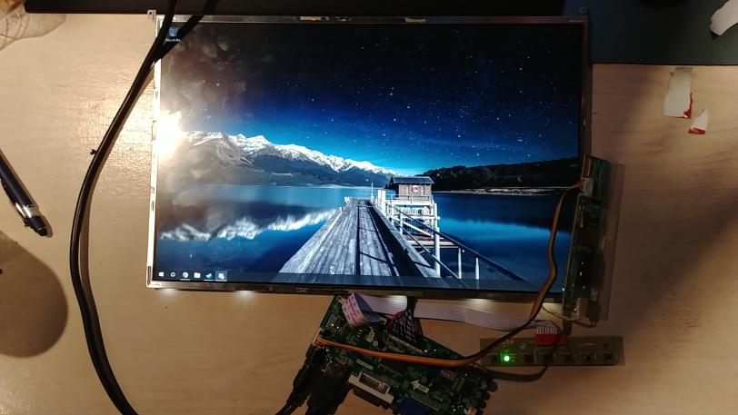
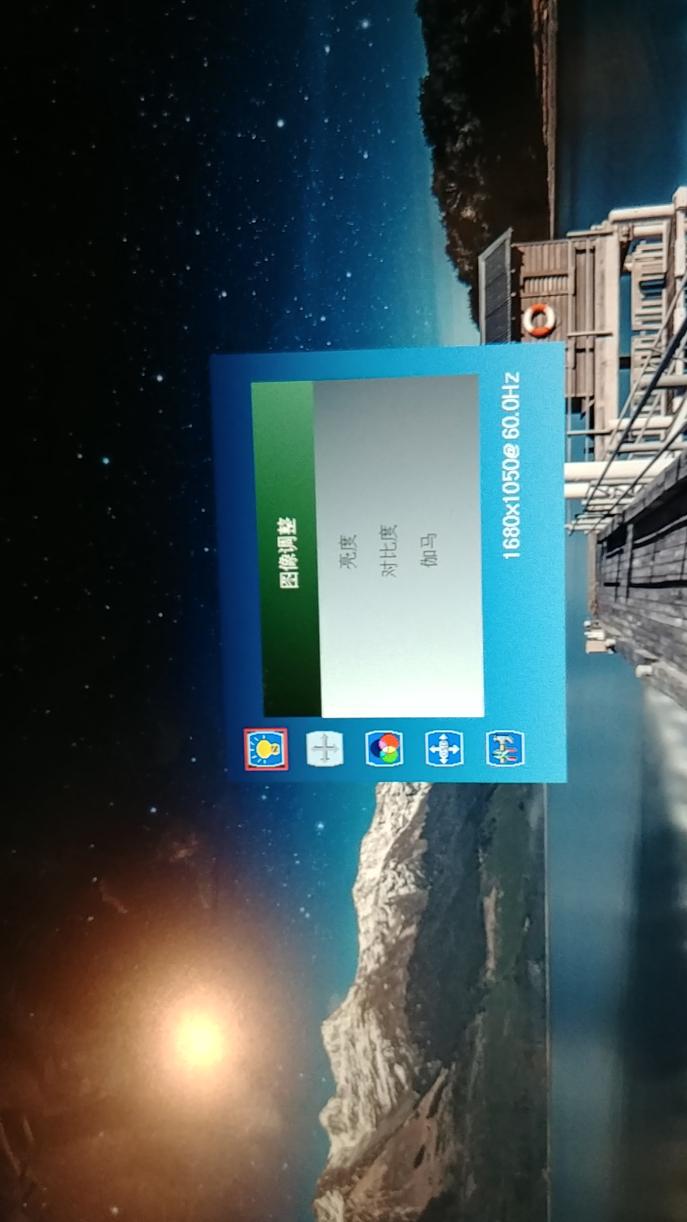
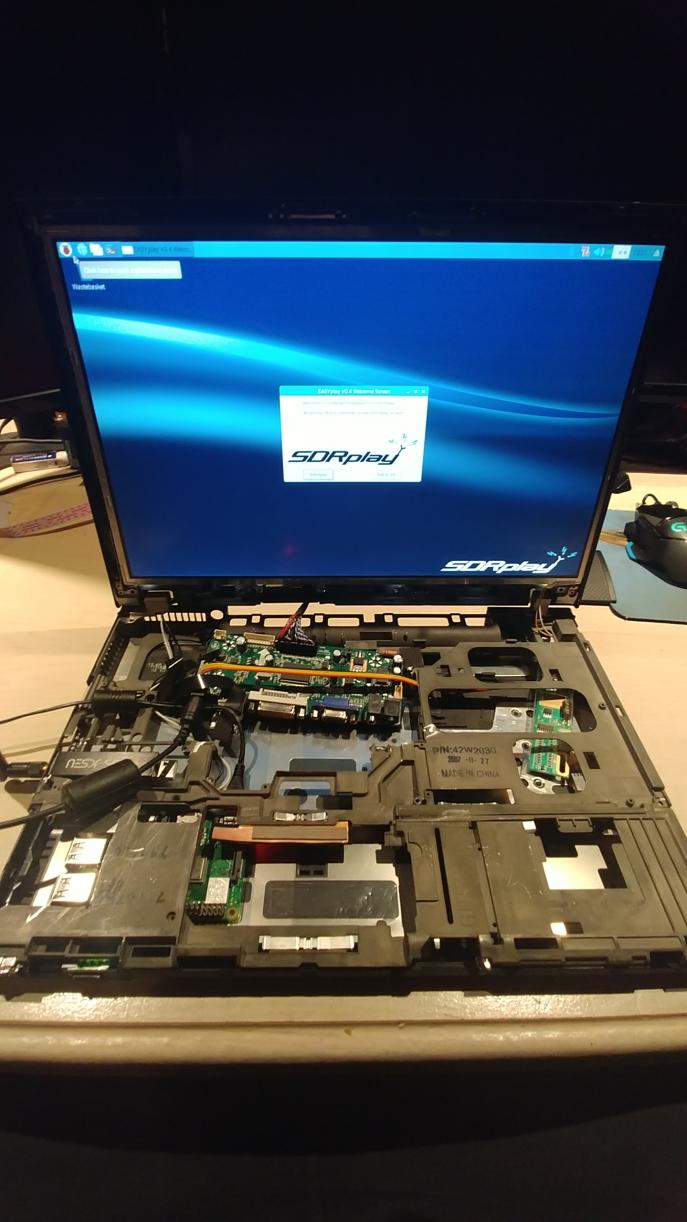
Finally though, It works. (Fig.4) And its flawless ! (Fig.5) And a great step forward to the completion of this project.
That's all for now
Next up : Keyboard or Power
Edit :
Oh right, I should maybe mention what the thing does.
Other than convert HDMI, DVI or VGA to the LCD's thing, I can also use speakers through it and use the AUX input too.
So the audio can go : Pi > Controller > Speakers
Or : Pi > Controller > Headphones / External
I have to adapt the included speakers though, the 4 pin plug is too small for the one on the controller, but I'm sure it will be fine.
This board does take a lot of power though, 12V 3A. That's about a typical laptop charger. so its going to need a beefy battery.

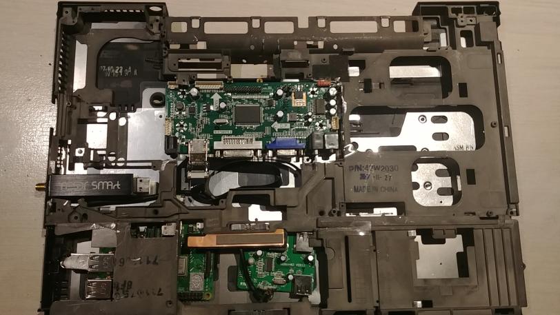
Update #2
Display controller fitment.
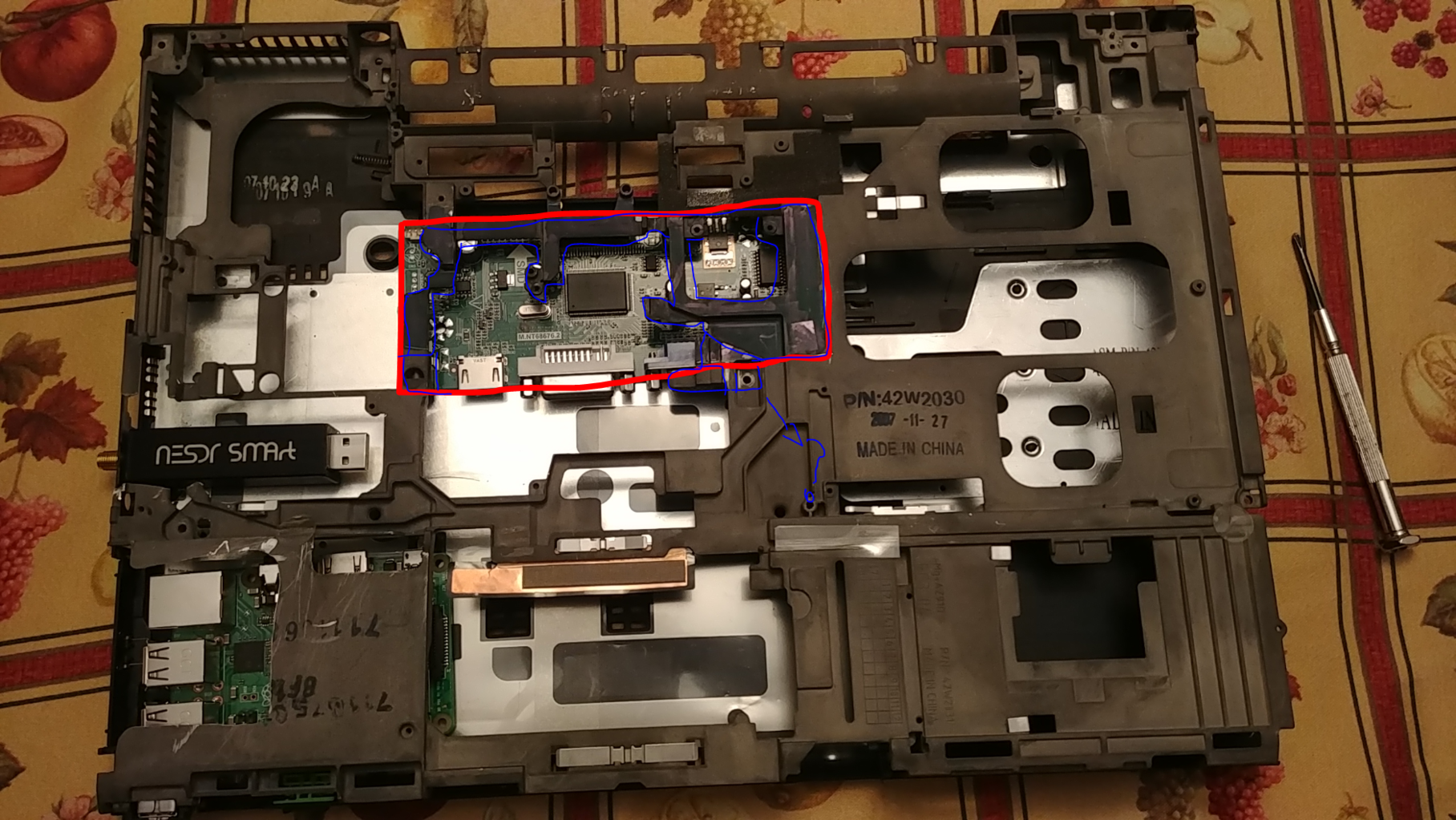
So I took the chassis apart again to see how the controller would fit (Did I mention how much this thing is awesome !?)(Fig.1)
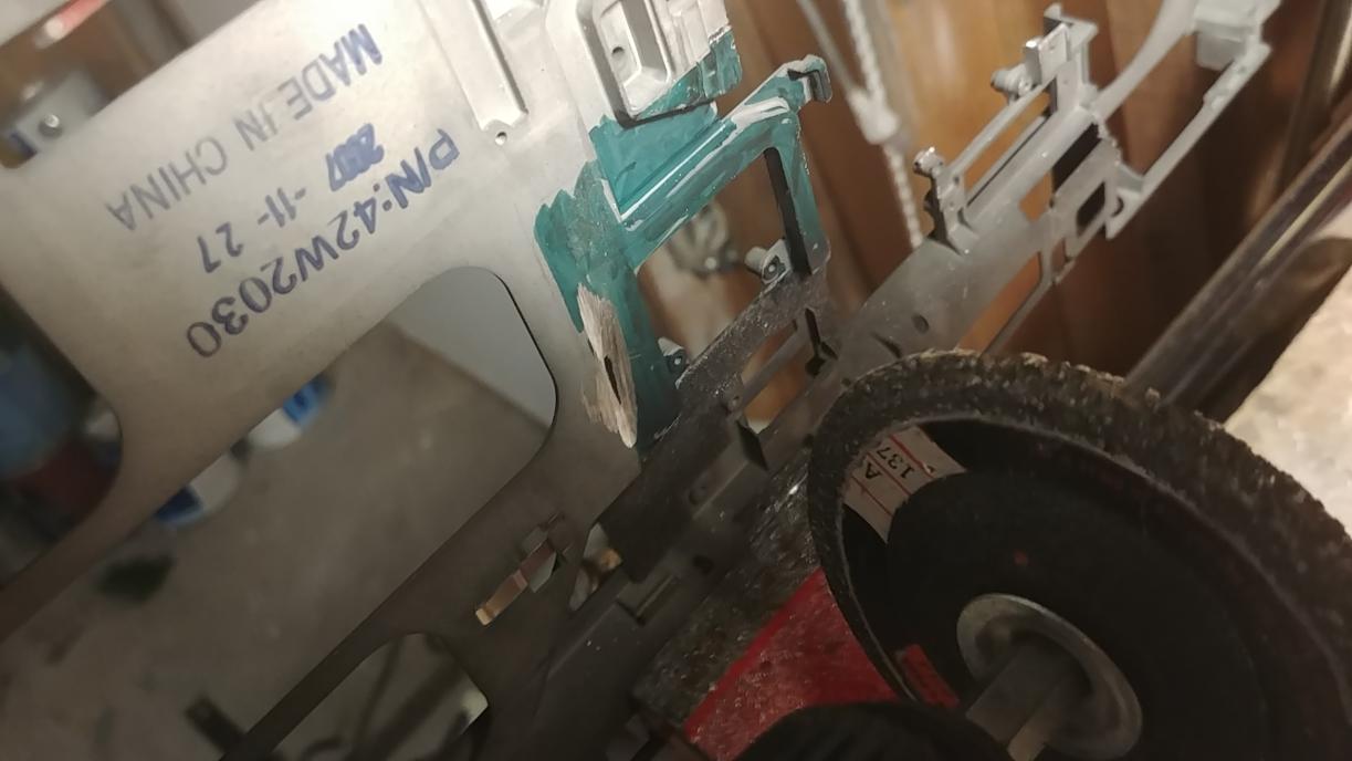
I had to cut a decent chunk off (Fig.2) and in the process, broke the cutting wheel on my Dremel (Fig.3).
As you can see, it fits pretty well in the chassis but will require more adjustments once I get another cutting wheel (Fig.4). The grinder + drill is too crude.
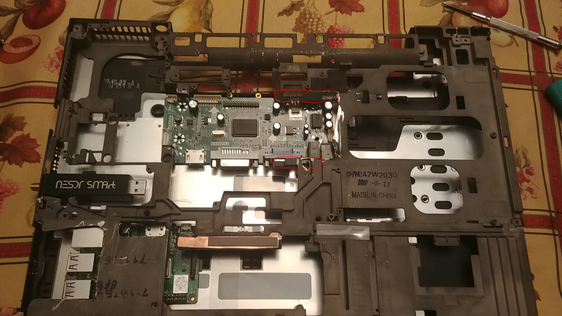
The board fits right in its place. it lines up perfectly with just about everything. I will however have to cap off the bottom of the laptop, as it stands right on top of the docking port hole. Furthermore, The LVDS cable for the monitor is too short (Fig.5) and will require an extension. I have not attempted to put the backlight assembly in yet, but since there's only 1 hole for cables to pass through easely, it will also need to be extended.
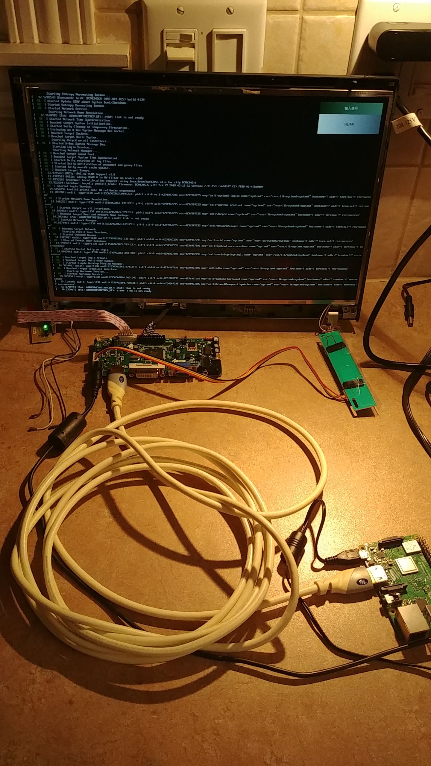
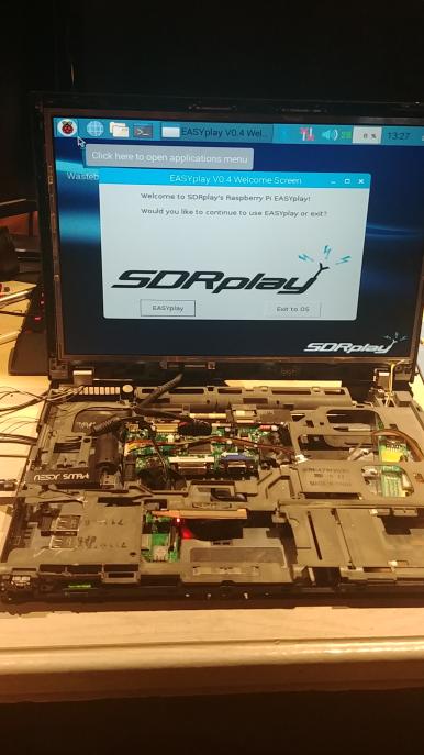
Finally, I have tested the LCD with the Pi outside the chassis, Its plugged in the wall for now, but not for long
(Fig.6)
Also, I don't have a picture of this, but this board is really good. the controller for the LCD has an unused IR receiver plug that outputs 5v witch could be (In theory) used to power the Pi. That would help a lot with the power delivery as I wouldn't need a 12v to 5v converter (though those car-to-usb controllers should work well). I just don't know how much current it can put out. and sadly, I don't think it can handle a Pi.
That's it for now
Update #3
Pi day ! (Ok, I'm a bit late, but this was meant on Pi day !! I promise !!)
Display adapter fitment is now final, final cuts on the frame to accommodate it are also done. here's a neat little picture of it, in place.
One major issue at the moment is that the LVDS cable is still very much too short (Fig.1), but I did manage to fit everything in and start it up ! (on wall power that is.)
Note : I've had to insulate the back of the PCBs from the metal frame and chassis. so I've used temporary some electrical tape. but I need to find a better, more permanent solution (any ideas ?)
That's it for now.
The electronics for the batteries will arrive one day.. (eBay is slow so eh..) and now I'm on a hunt to find a cheap and easy solution to extend the display cable !
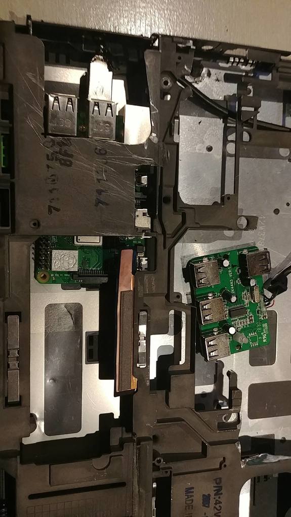
Edit : I forgot to mention that I bought a usb splitter for the sake of wiring convenience (and to not have to strip any other cable of their wire reliefs)
They are a pain in the ass to strip, and the usb male Port is a long boi, but it fits, just right.
Update #4
The display controller extension cable is here ! (LVDS)
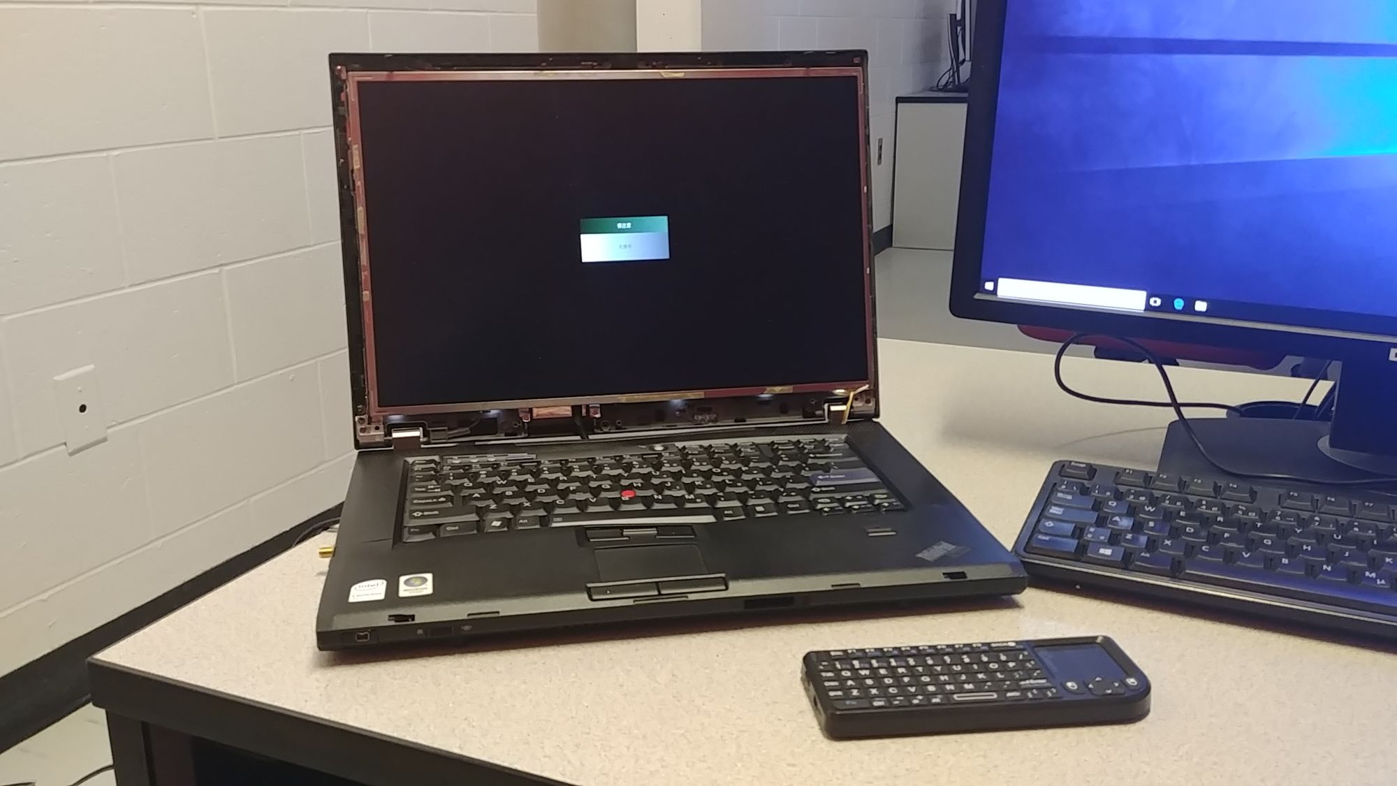
Here's a size comparison with the 25cm one (new is 40cm) (Fig.1) Also, I have been using this Bluetooth keyboard+trackpad combo since I got news from the maker of the keyboard converter, he doesn't have any to sell me but told me he was working on updating his design. I also fit the power cables inside the laptop (Fig.2) so that I don't have to take it apart to plug anything in.
This however is temporary and I have ordered panel-mount extensions so that the cables can be externally plugged in, rather than looking like the laptop is carrying an IV bag around.
Here's a link to the LVDS extension (This link has been hard to get, believe met though if you order the board, simply tell them that you want the 40cm cable). As well as the panel-mount extensions I have ordered :
LVDS Cable
Barrel Jack (12v input)
USB adapter (I used the B to microB because it's got a better connector imo)
USB Left right angle extension cable (since the usb on the pi is so close to the side of the laptop, might only be able to use 2 tho)
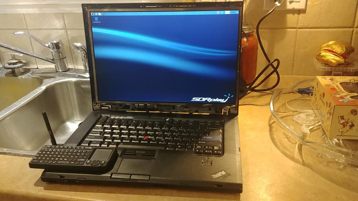
And finally here's the laptop turned on with the screen upright and the electronics in their correct position (Fig.3) And with the panels on top (Fig.4)
And finally, All screwed down ! (Fig.5) I really love that it's got some sort of "IV bag" to carry for it's life support (the power adaptors) (Fig.6) And I even brought it to college ! (Fig.7) However, it seems I have messed up something closing it down, since the screen turns on but not the pi (Probably one of the pins is shorting, but really an issue.. I just need some more electrical tape ?
That's it for now !
Hopefully I get the rest of the parts soon so that it's easier to carry, I will probably just edit this post once it's back in working order (It's only 8 screws, some tape and voila!)
Thanks again for taking the time to read.
Comments?
Leave us your opinion.